

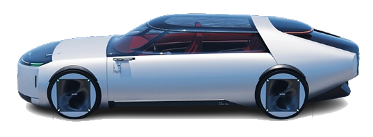
01CONCEPT DESIGN
Styling Concept
Define brand direction, vehicle proportion, volume and design language, from creative decisions to styling data input.
CORE DESIGN & ENGINEERING CAPABILITY
Define brand direction, vehicle proportion, volume and design language, from creative decisions to styling data input.
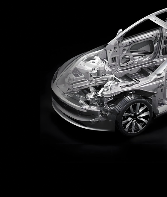
Coordinate Exterior, Interior, Body, Closures and system interfaces in parametric 3D data, turning styling intent into manufacturable structures.
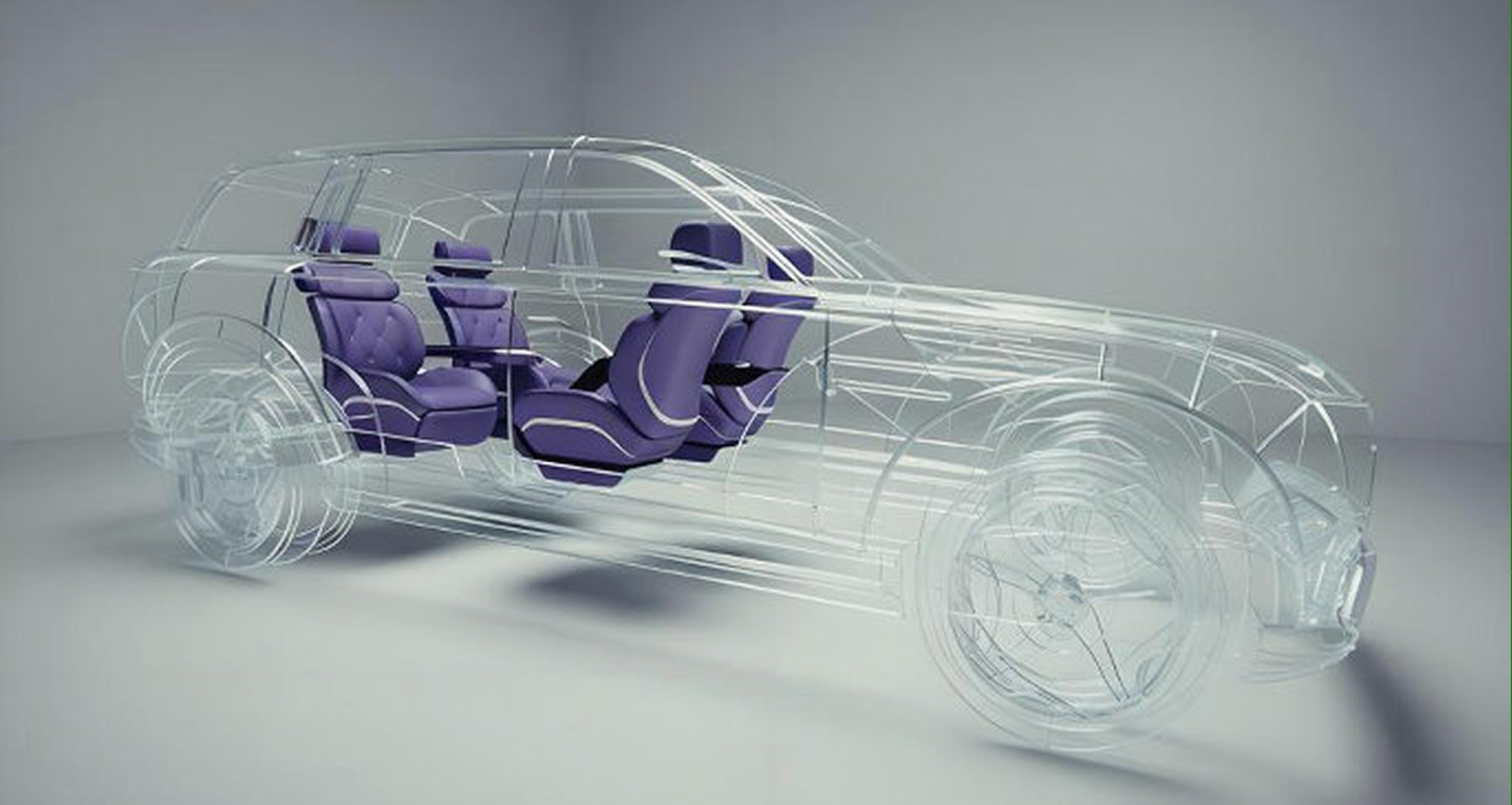
Use structural, safety, NVH, CFD and occupant-protection analysis to identify risk and drive design optimisation before physical validation.
CHTAE covers styling concepts, engineering design and simulation. Engineering design connects Exterior, Interior, Body, Closures and Integration, while digital analysis drives convergence before prototype build.

Coordinate structure, regulations, manufacturing and assembly for front and rear bumper systems, converging the styling A-surface and internal mounting strategy in one data chain.
PRECISION MATCHING & DELIVERY
Turn the styling A-surface into a complete, reliable and production-ready bumper system, coordinating visible parts, internal structures, sensors, mounting limits and service strategy.
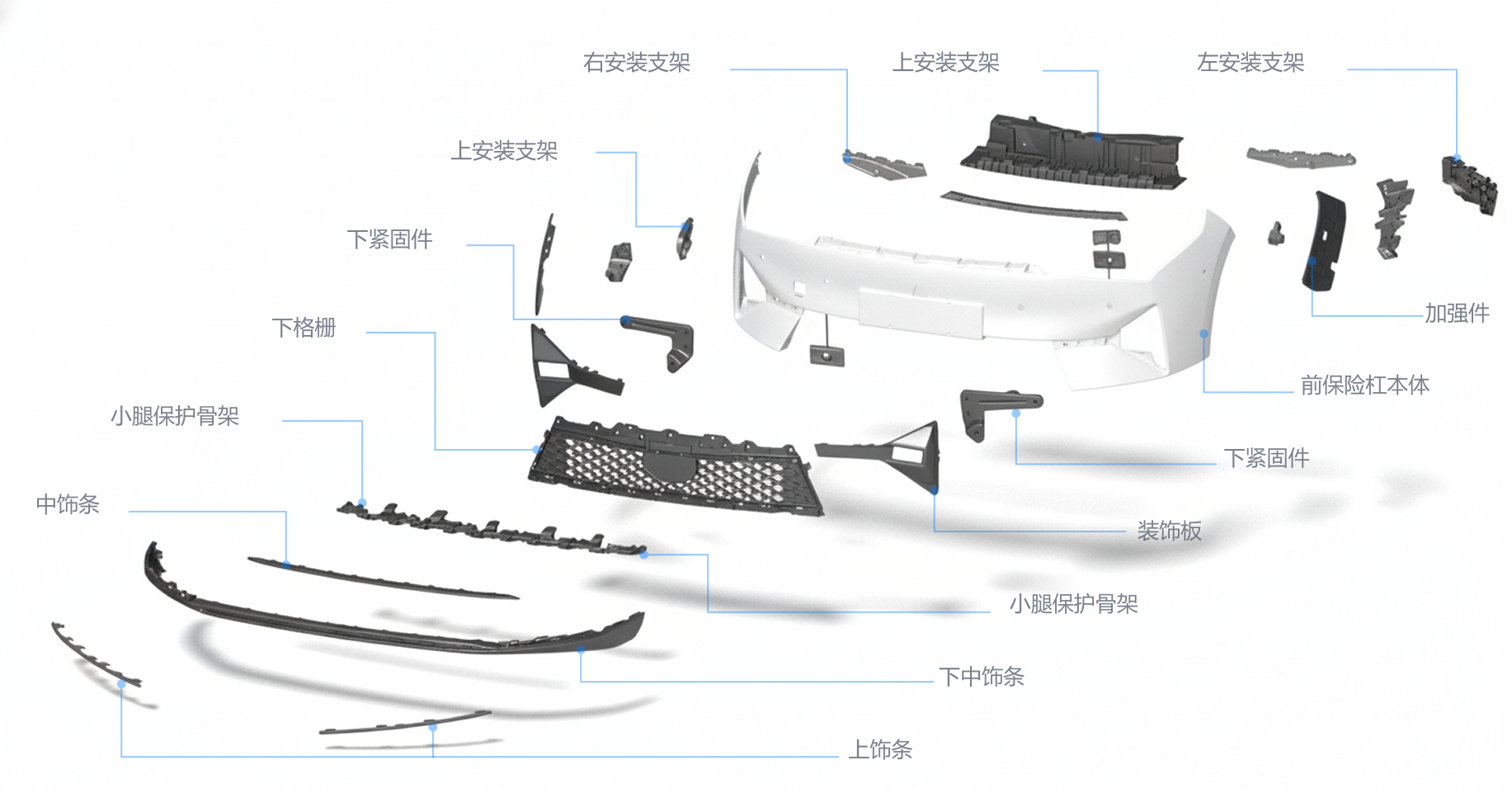
Cover the bumper fascia, grille, trim, brackets, fasteners and energy absorbers, defining complete assembly boundaries from visible parts to internal structures.
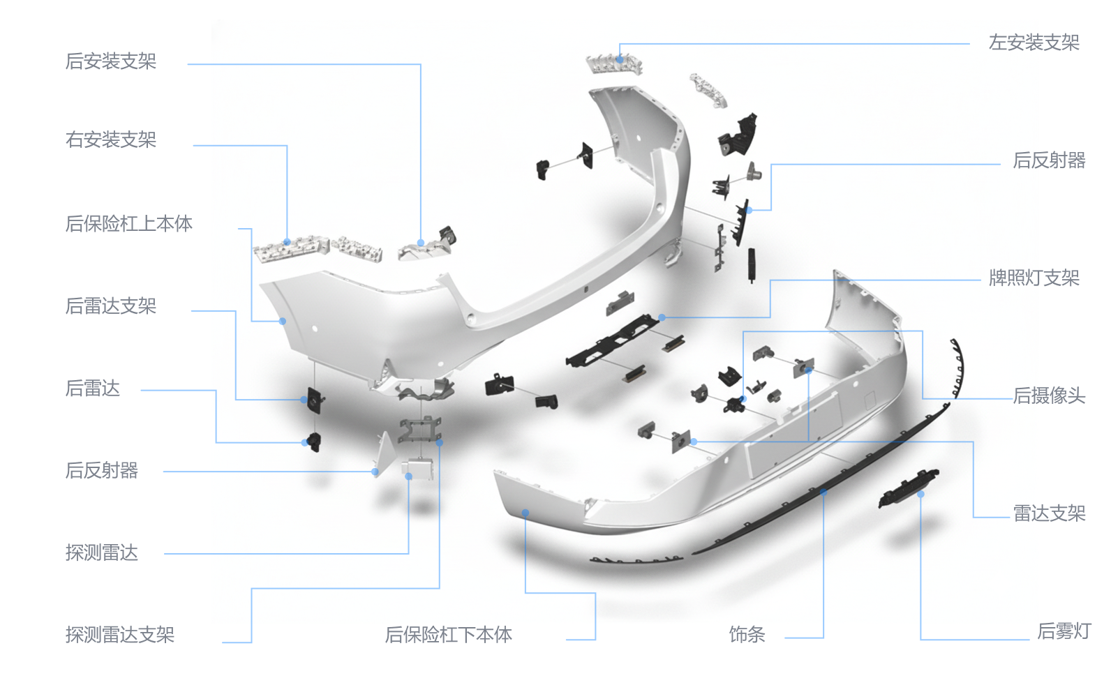
Coordinate radar, reflectors, license-plate lamps, cameras, fog lamps, trims and brackets, locking down sensing, service and assembly interfaces early.
02 / INTERIOR ENGINEERING
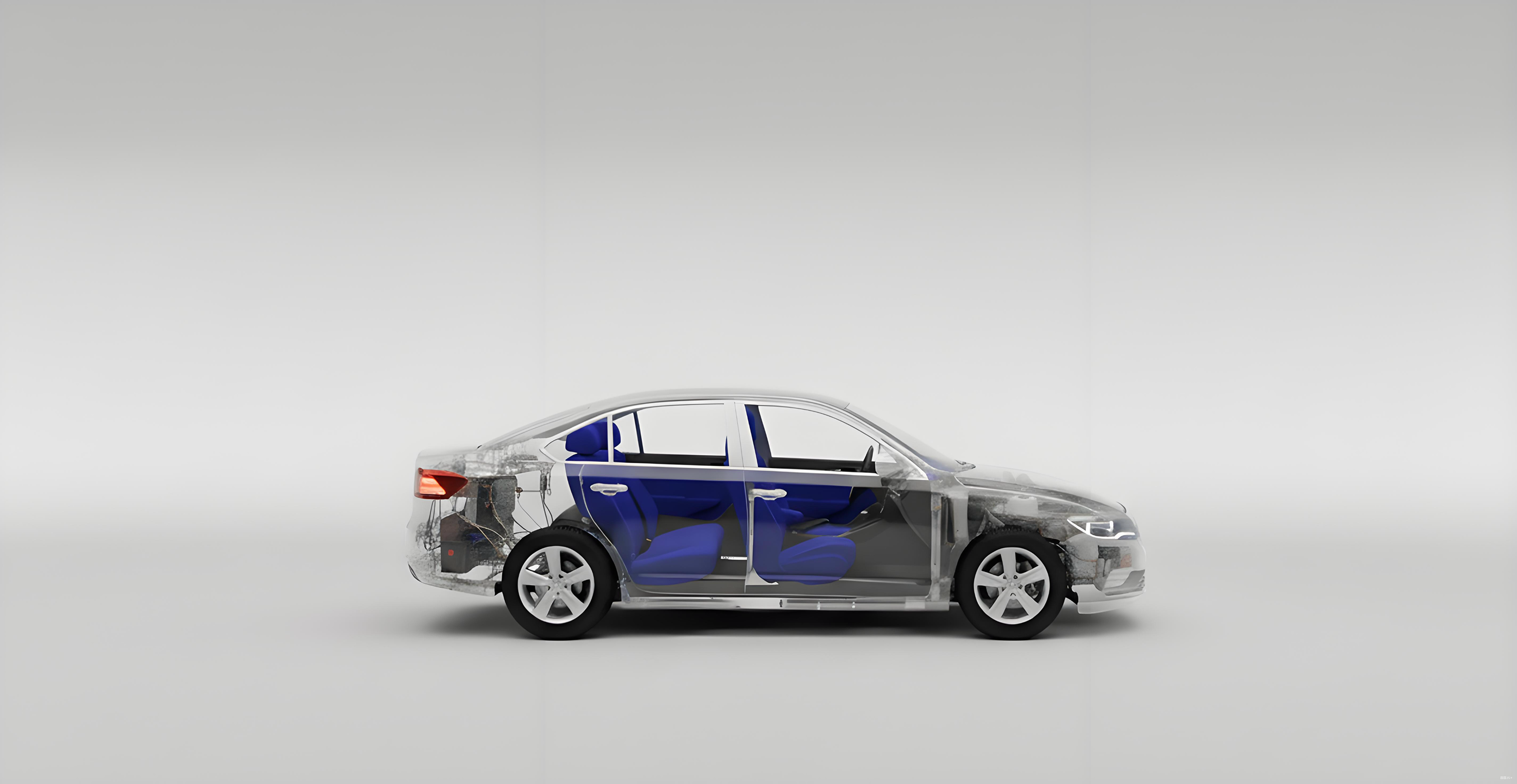
Develop interior modules into verifiable, assembly-ready and production-ready systems across visibility, cabin comfort, functional integration and perceived quality.
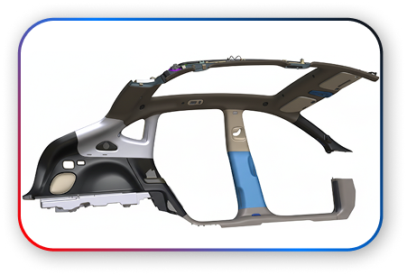 •Safety and Visibility Structure
Reserve a reliable curtain-airbag deployment path and optimize the A-pillar section to reduce the driver's blind zone.
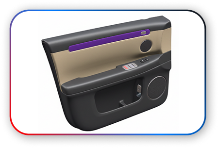 •Function Integration and Perceived Quality
Integrate speakers, ambient lighting and switches while optimising acoustics and mounting structures to reduce squeaks and rattles at source.
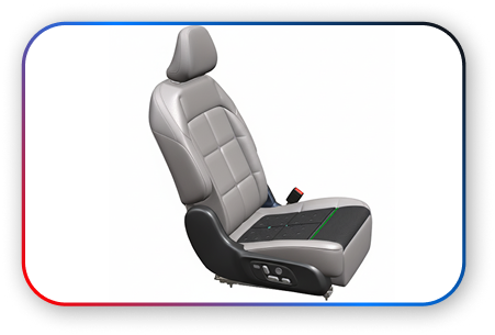 •Safety, Comfort and Technology Combined
Develop a high-strength seat frame for global crash regulations, then apply ergonomic foam and trim design for comfort.
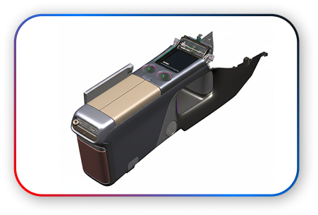 •Functions and Ergonomics, Precisely Integrated
Optimize ergonomic layout and internal mechanisms to integrate shifting, storage and electronic modules within a compact space.
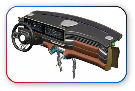 •Core Structure for Vehicle Performance and Safety
Engineer instrument-panel cross-car-beam stiffness and NVH while ensuring seamless integration and reliable deployment of the driver airbag.
03 / BODY ENGINEERING
Establish a production-ready structural foundation by balancing safety, performance, lightweighting and cost across load paths, joints, dimensional quality and manufacturing processes.
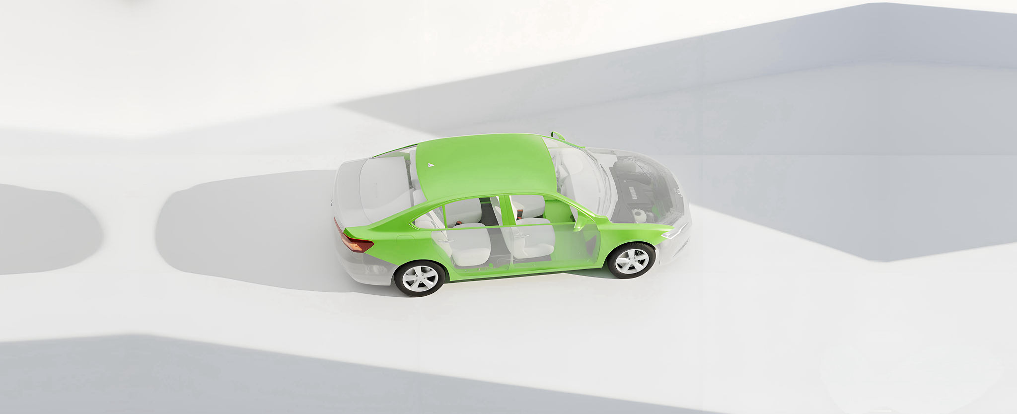
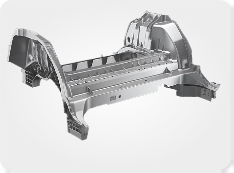 01Integrated Die Casting: Process Shift
Replace multiple welded parts with large castings to reduce joints and improve dimensional stability.
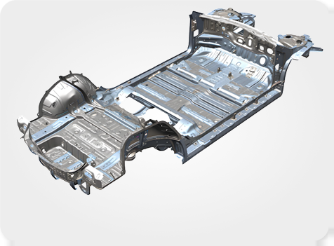 02Underbody Assembly: Load-Bearing Base
Build a high-stiffness platform and optimize crash-load transfer and NVH performance.
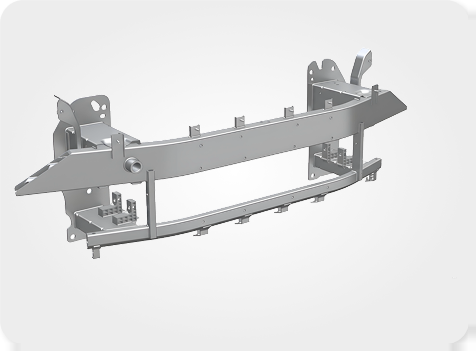 03Front Crash System: Energy Shield
Absorb and distribute crash energy efficiently while balancing regulations and repair cost.
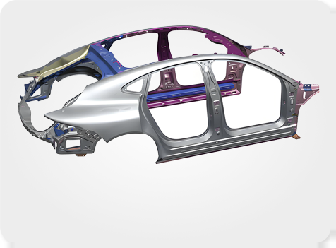 04Upper Body: Safety Cage
Create a complete occupant-cell safety cage with greater ring stiffness and assembly precision.
04 / CLOSURES ENGINEERING
Coordinate motion, sealing, durability, lightweighting and operating quality so every closure system performs reliably in real conditions.
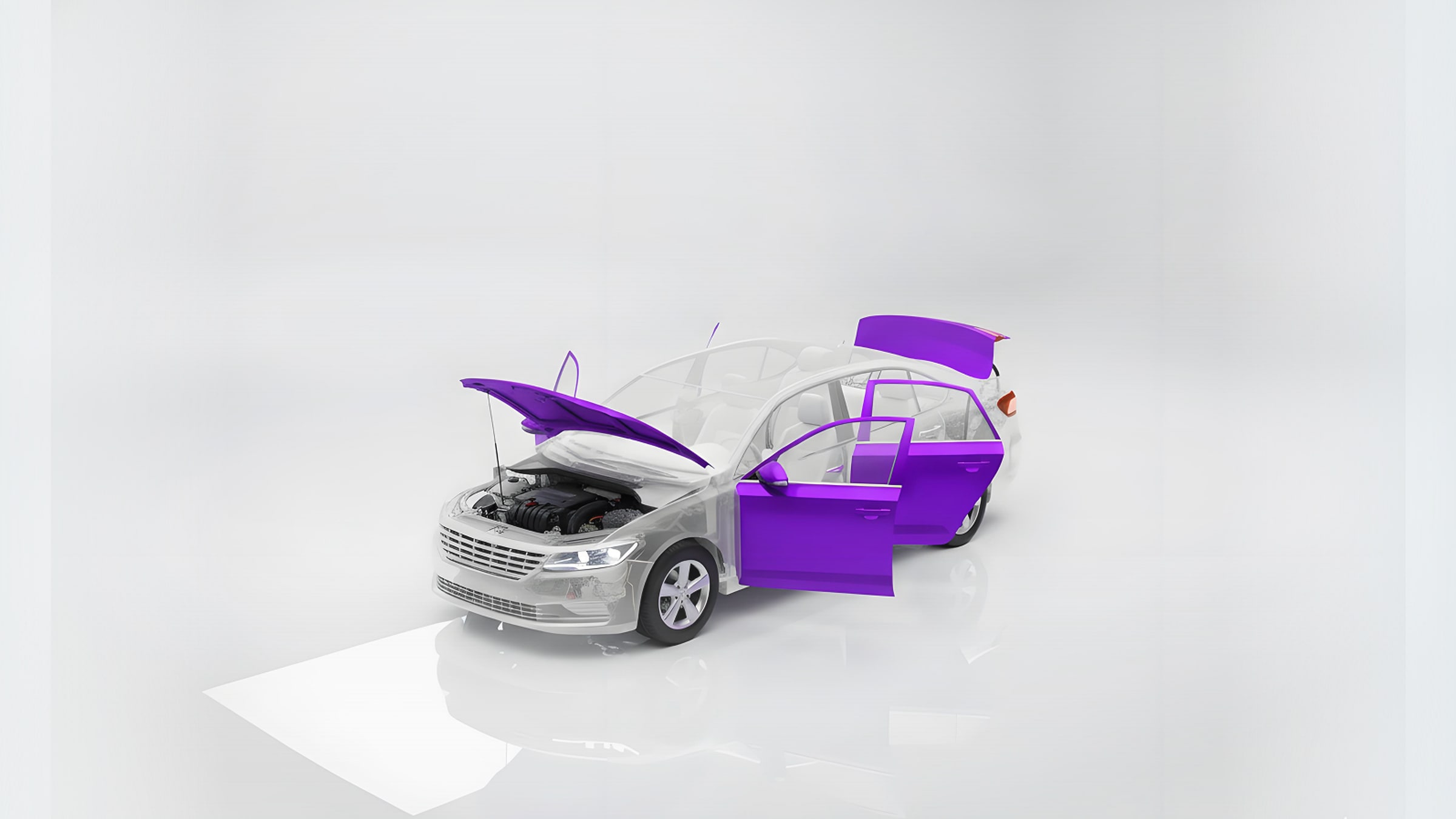
Balance pedestrian protection, high-speed flutter resistance, and latch and hinge system design.
Coordinate the opening path, sealing system and powered operation.
Coordinate gap and flush, structural performance and child-safety lock integration.
Coordinate side impact, NVH, closing quality, and window lift and guide design.
05 / SYSTEM INTEGRATION
Use vehicle hard points and vehicle datums to coordinate electrical systems, thermal management, lamps and module packaging, identifying interference, clearance and assembly risks early.
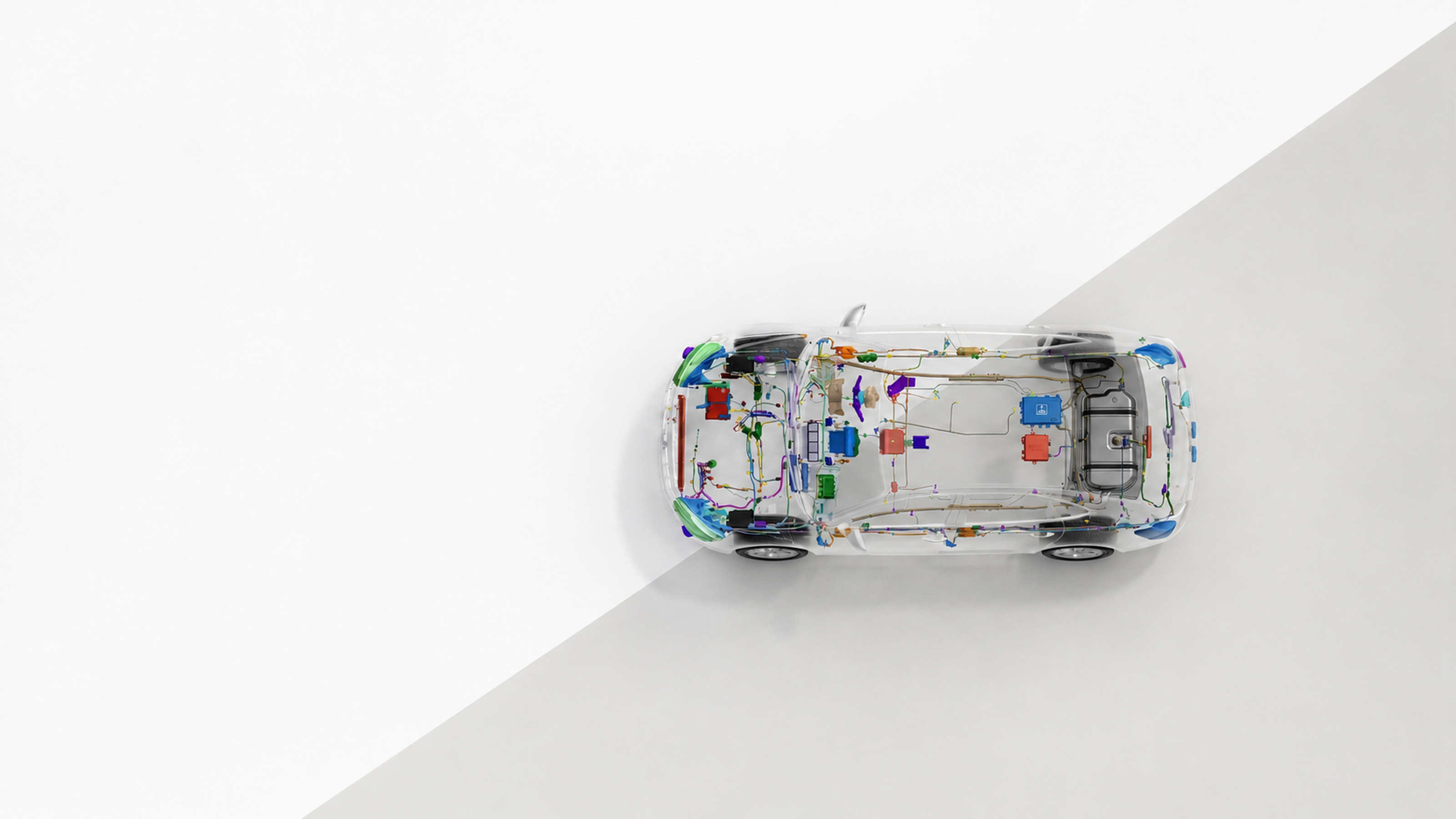
Plan 3D routes, fixing points, clips and channels, then verify interference and assembly access.
Coordinate the HVAC unit, ducts, brackets and pipe interfaces to meet defrosting and NVH requirements.
Verify hard points, boundaries, motion envelopes and assembly sequence across disciplines.
Develop lamp structures and mounting boundaries while balancing regulations, sealing and styling execution.
Optimize module boundaries, mounting points and removal space for service and manufacturing feasibility.
Coordinate suspension, steering and braking interfaces with the body, checking motion envelopes, hard-point relationships and assembly boundaries.
DIGITAL SIMULATION
Turn complex physical problems into comparable, traceable engineering conclusions, evaluating structure, safety, NVH, fluids and occupant protection before prototype build.
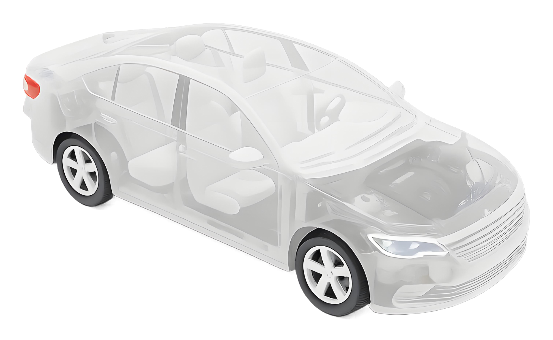
07 / ELECTRICAL & VEHICLE TEST
围绕整车电器功能、连接关系与接口状态开展检查和验证,协同记录测试结果、跟踪问题并支持闭环。
INTEGRATED CAPABILITY
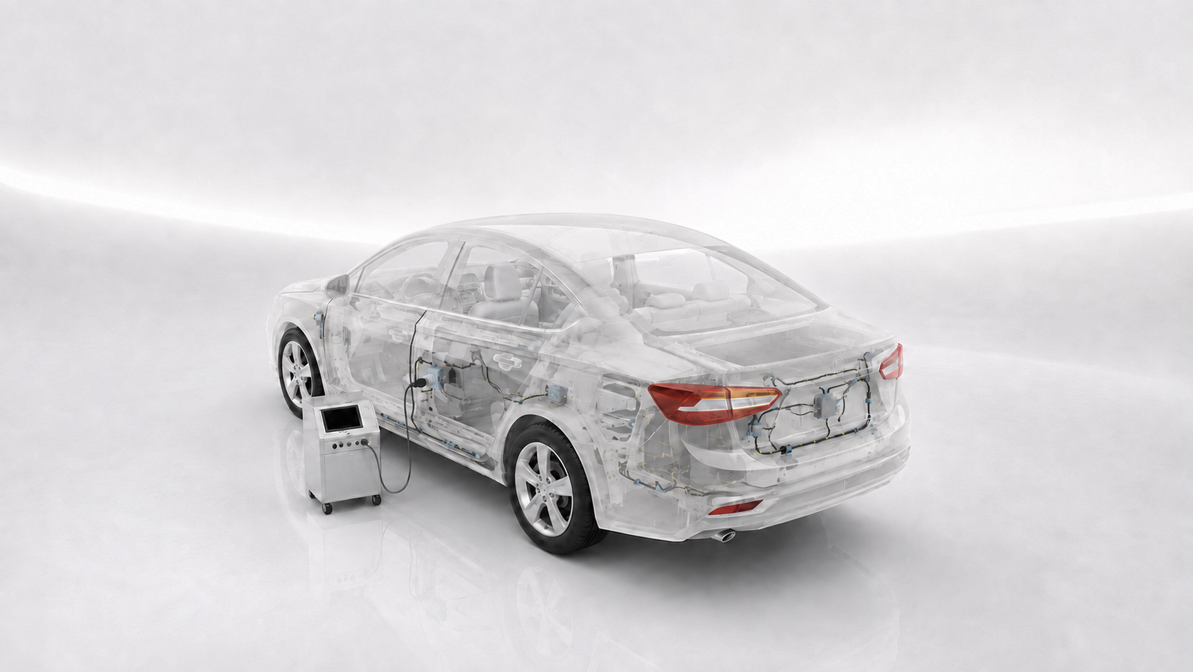
CHTAE connects styling concepts, parametric engineering, digital prototypes and multiphysics simulation in one data chain, giving every design decision a clear engineering basis and converging toward a manufacturable, verifiable production solution.
Define vehicle proportion, stance, design language and surface direction.
Connect engineering development through parametric 3D data.
Control hard-point, section, interface and assembly-data precision.
Coordinate five engineering disciplines with digital simulation.
Cover structure, safety, NVH, fluids and occupant protection.
Check interference, clearance, motion envelopes and assembly access.
Feed simulation conclusions back into engineering optimization.
Connect prototype build, suppliers, issue closure and delivery milestones.
From styling input and engineering data to simulation conclusions, CHTAE moves validation into the concept phase, identifying structural, packaging, performance and manufacturing risks early and driving continuous convergence with clear engineering evidence.
CAD, CAE, DMU and project milestones share one data chain, connecting prototype build, supplier collaboration and issue closure to support production quality, development efficiency and final delivery.